- Home
- >
- Software Development
- >
- Use a Servo as a Gauge – InApps Technology 2022
Use a Servo as a Gauge – InApps Technology is an article under the topic Software Development Many of you are most interested in today !! Today, let’s InApps.net learn Use a Servo as a Gauge – InApps Technology in today’s post !
Read more about Use a Servo as a Gauge – InApps Technology at Wikipedia
You can find content about Use a Servo as a Gauge – InApps Technology from the Wikipedia website
Gauges are valuable visual output devices for hardware hacking and Steampunk projects. A gauge, at its most basic, is a component that measures something, offering a numerical or visual representation of the magnitude of what it is measuring.
My weekend home project prototypes combine both of these themes, so I figured it was a good time to actually put a gauge into a project.
For the color LCD screen of my next Steampunk conference badge, for instance, I thought it would be a no-brainer to create a simple gauge from software.
It turns out that designing on-screen gauges are more complicated than I thought. First, I couldn’t find any “gauge” libraries for Python, the most used programming language for the Raspberry Pi. Processing was an option since there are some nice libraries for knobs. I’ve hacked a few of those examples into usable gauges, for past projects. Of course, processing has to be installed on the Pi first. I hadn’t looked at those programs in quite a while, so decided to put “on-screen” gauges on the back burner, for now.
Why not use a servo as a gauge? That’s what watch and car makers use. How hard could it be?
Here’s a hint. A lot depends on the sensors and timing. This week, we’ll look at how a servo gauge might work in your projects, along with lessons learned and challenges faced.
Attracting Attention
My conference badges are designed to attract attention and spark conversation when worn to an event.
I included an ultrasonic range finder, on my next, “Generation 5,” badge, because not only did it look interesting, it would also act as a “social interactivity inferometer” sensor. That’s a fancy made-up Steampunk technical term for a device that measures the distance between myself and another person, as well as, our level of interaction.
If nobody’s in front of me, the ranger would report a high number or even “out-of-range” value. Normal, casual conversion might return a value of 36 inches. A measurement of 12 inches or less would mean we were carrying on a close and perhaps spirited discussion.
To provide visual feedback, I thought a moving gauge, on the front of the badge that changes with distance, would spark a few queries.
In the case of the conference badge, the ultrasonic range finder is attached to a couple of pins on the auxiliary Arduino Pro Mini microcontroller. The Pro Mini sends serial data to the Raspberry Pi that then displays the text values in a terminal. I used the ping example from the sensor library for the basic Arduino code.

Auxiliary Arduino Pro Mini unmounted from under the Raspberry Pi board
The range finder data can also feed a servo attached to the Pro Mini directly, with a few mods to the ping code.
Here are the essential connections of the circuit diagram for the ultrasonic sensor, the servo, and the Arduino Pro Mini:
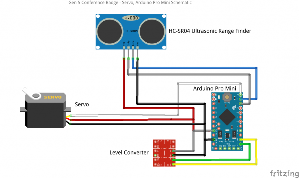
Basic connections for the ultrasonic sensor, the servo and the Arduino Pro Mini
Reflecting on Input Data
The ping code it fairly straightforward. Send out a ping, measure the return time, convert the time to distance, then print the result. The additional code needed to run the servo is in bold.
1 2 3 4 5 6 7 8 9 10 11 12 13 14 15 16 17 18 19 20 21 22 23 24 25 26 27 28 29 30 31 32 33 34 35 36 37 38 39 40 41 42 43 44 45 | /* HC-SR04 Ping distance sensor] VCC to arduino 5v; GND to arduino GND Echo to Arduino pin 7; Trig to Arduino pin 8 */
<strong>#include <Servo.h> Servo myservo; // create servo object to control a servo</strong>
#define echoPin 8 #define trigPin 7 <strong>int val;</strong>
void setup() { Serial.begin (115200); pinMode(trigPin, OUTPUT); pinMode(echoPin, INPUT); <strong>myservo.attach(9);</strong> }
void loop() { // send a pulse on the trigger pin to initiate measurement digitalWrite(trigPin, LOW); delayMicroseconds(2); digitalWrite(trigPin, HIGH); delayMicroseconds(10); digitalWrite(trigPin, LOW);
// the length of the pulse on the echo pin is proportional to the distance long duration = pulseIn(echoPin, HIGH); long distance = (duration / 2) / 29.1 * .3937 ;
if (distance >= 200 || distance <= 0) { Serial.println(“Out of range”); } else { Serial.print(distance); Serial.println(” in”); }
val = map(distance, 1, 70, 0, 180); // scale it to use it with the servo (value between 0 and 180) myservo.write(val);
delay(300); } |
The servo code isn’t anything complicated either.
First, the include statement pulls in functions from the standard servo library, while the Servo statement initializes the object used to control the servo.
We have to add a variable, val, for use in scaling the distance value from the range finder to an angle value, as needed by the servo control routines.
Next, the myservo.attach statement assigns the servo to pin 9 on the Arduino Pro Mini.
After that, the map function scales the distance to the angle for the servo and then that value is written to the servo, to make it move.
I made sure to set the board to “Pro Mini”, under the Tools menu in the Arduino IDE. If you forget and compile the code with a different board, you’ll get a “stk500_getsync()” error when you try to upload the firmware to the Pro Mini. Switch to the correct board and everything will work fine. Start the Arduino IDE with sudo to avoid problems with USB port permissions
pi% cd ard*1.6.5 pi% sudo ./arduino |
The code was developed on my Linux notebook and uploaded using a USB to serial interface cable. After the code was compiled and uploaded to the Arduino, I removed the cable and rebooted the Pi on the conference badge. Once, the Pi was up and running I switched on the power to the Arduino and the servo immediately began moving.
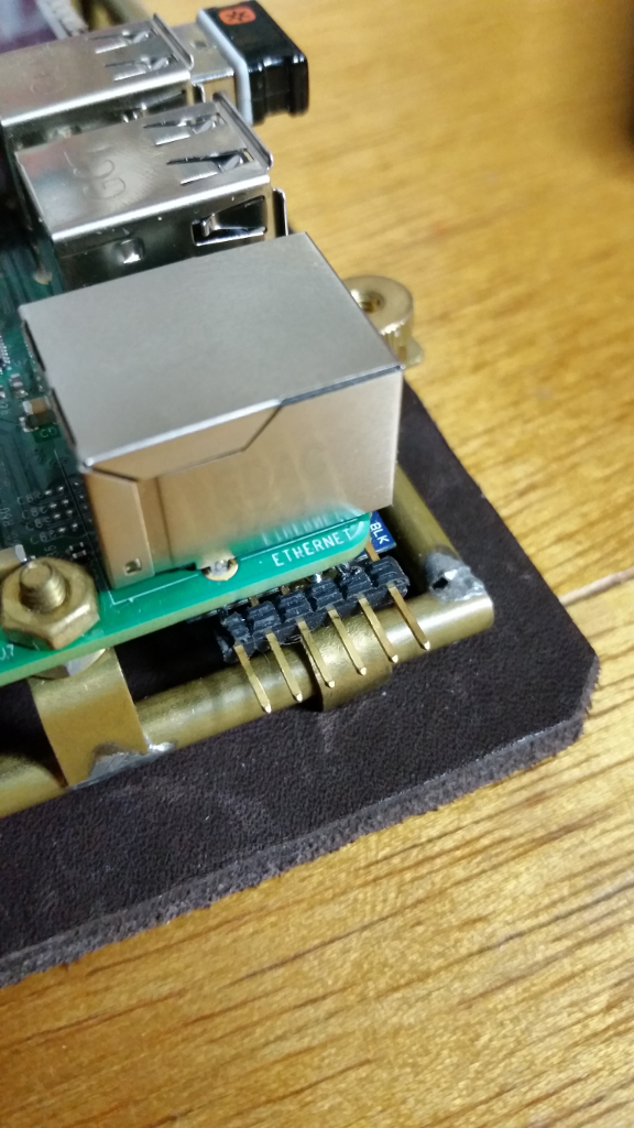
Serial to USB header connection to the auxiliary Arduino Pro Mini
Are Servo Gauges Viable on the Badge?
The results were a little disappointing. The servo kind-of worked, but its action was pretty erratic.
After watching the data from the serial terminal, as the ultrasonic range finder fed data to the Pro Mini and attempted to track it with the servo, it becomes obvious that timing was a major issue.
The ultrasonic sensor uses two data lines. One sends a digital pulse to the transducer on the sensor. The other line hooked up to the sensor receiver listens for the digital pulse to return and then the Arduino converts the round-trip time of the pulse into a distance.
The Arduino also generates a specific-width pulse, to tell the servo to move to certain a position.
The little Arduino just didn’t seem to be able to accurately generate and read those pulses for both the ultrasonic sensor and servo at the same time. Making matters worse, anything that creates a delay in code execution causes further problems with the timing. The Changing delay() function values and even adding print statements had negative effects on servo tracking.
Another problem might be noise from the servo motor affecting the power going to the ultrasonic sensor on the +5 volt power line. Some filtering or a separate power supply for the servo might be helpful.
My conclusion is that using an ultrasonic range finder and servo gauge, in this configuration together, was a problematic combination for my particular application.
Reading a potentiometer with an Arduino’s analog input pin then moving a servo (say for a gauge), according to the value, is pretty reliable. I’ve used this technique lots of times, for remote control projects. The potentiometer on an analog pin doesn’t really care about pulse widths and timing problems. The results are consistent, fast and tracking is pretty good. If your sensor doesn’t have a strong timing requirement, using a servo as a gauge would work in a lot of cases.
Before adding the servo to the badge, the range finder went merrily along its way, tracking distances at a few times a second, while spitting out the values as a text stream in a terminal window. Values were consistent, fast and accurate. You could use a range finder and have the Arduino manage the timing, a servo gauge, hooked to an output pin. You could also investigate an external I2C-based servo driver board. I have doubts about those approaches, though.
What Would Work Better?
I’ve wanted to add a tricolor LED “ozone tube” to the Gen 5 badge for a while. Even though the LED is controlled with pulse width (PWM) output values, it might work as a visible output device. Imagine the LED changing from blue, through green, to orange, then red as someone gets closer to the badge. We’ll have to give it a try.
Or, maybe an on-screen gauge would work better after all. I don’t see any reason that timing issues would affect a gauge displayed on the LED screen. Maybe it makes sense to hack one of my old Processing gauge programs (on the Pi) to read the range-finding data fed from the Pro Mini into the Pi’s serial port. This option is a good candidate for a future column.
Off-The-Shelf Hackers frequently go through false starts and do-overs. It’s the nature of the game and how we learn. Veteran designers certainly are aware of timing challenges when working with microcontrollers and act accordingly.
There are huge gaps in knowledge and understanding between the pro and weekend hardware builders. Look around and see if you find real-world discussions of timing, sensors and microcontrollers.
InApps Technology is a wholly owned subsidiary of Insight Partners, an investor in the following companies mentioned in this article: Shelf.
Source: InApps.net

Let’s create the next big thing together!
Coming together is a beginning. Keeping together is progress. Working together is success.